Solid-State Microphone Preamplifier
For the final project in my analog and digital electronics course, I designed and built a solid-state microphone preamplifier. The preamplifier initially was meant to be a small, portable device; however, it morphed into a rack-mountable piece of equipment after I was able to acquire an inexpensive chassis. The device is the first project that I truly designed, and it is one of the first pieces of gear that I built. It offered the standard functionality of an external preamplifier: switchable gain, polarity flip, phantom power, level meter, and balanced I/O.
Project Description
Throughout the history of audio engineering, many pieces of gear have emerged as defining examples of high fidelity audio. Some famous examples of quality preamplifiers include the Neve 1073, Tube-Tech MP1a, and API 312. However, many of these devices are far too expensive for the average enthusiast and are realistically only within the budget of a professional studio. The goal of the project was to construct a microphone preamplifier without the typical expensive components.
People are willing to pay a lot of money for preamplifiers due to their importance: they are the first device that a microphone sees in a conventional signal chain. Its primary function is to take a microphone signal, usually around 10-100 millivolts, and boost it up to nominal line level. It should be noted that there are actually two standard line levels that have emerged in the audio industry, one being consumer line level and the other being professional line level. Consumer line level is rated at -10 dBV or approximately 0.316 VRMS; professional line level is rated at +4 dBu or approximately 1.23 VRMS. Aside from the diversity in amplitudes, there are other signal differences that a preamplifier needs to account for as well. Some microphones, usually condensers, do not have an internal power supply. This means that preamplifiers need to be able to provide a standard +48 V DC voltage for some mic inputs.
The other common function that users expect a preamplifier to provide is a polarity switch (usually wrongly labeled a “phase” switch). Some recording situations create dual mic signals that have the opposite polarity. For example, it is common to record the bottom and top head of a snare drum with different microphones. When a stick hits the drum, the top head is pressed in while the bottom head is pressed out. Thus, the top microphone captures air rarefaction while the other mic captures air compression and vice versa. Thus, the two signals would cancel out, in theory, when mixed together unless the polarity on one of the signals is flipped.
The wide variety of possible input signals creates a technical challenge. How does one accommodate every possible scenario when designing a preamplifier? The typical answer is by offering a high amount of gain and a wide variety of controls. Most preamplifiers offer the same user controls: phantom power, gain, mic/line switch, and phase. Many preamplifiers also offer a meter to view the audio level. I decided to add a logarithmic audio meter using an LED driver.
The parts that are mainly responsible for driving up the price of a preamplifier are the power transformer, signal transformers, vacuum tubes, discrete transistors, and steel chassis. The design process for this project involved analyzing classic preamplifier schematics and finding budget alternatives for these price-intensive parts. Upon examination, it became clear that the function of most of these components could be replicated through the use of operational amplifiers. Op amps are able to convert a balanced signal to an unbalanced signal, an unbalanced signal to a balanced signal, and vary the amplitude of a microphone signal. In theory, this means that they are able to replace signal transformers, vacuum tubes, and discrete transistors. The part that an op amp could not replace is a power transformer. The power transformer is responsible for converting the mains outlet voltage to more usable voltage sources via its secondary windings. The voltage sources that are typically needed include +48 volts for phantom power, +24 volts for discrete transistor stages, and +200-300 volts for vacuum tubes. In order to retain the original low budget, the power transformer was replaced with a wall wart that could provide a regulated +48 volts. From there, a DC-DC converter was used to convert the +48 volts to ±15 volts for the op amps, and an additional voltage regulator was used to convert the +15 volts to +5 volts for the LED driver.
The circuit takes a balanced microphone signal from an XLR input jack, and it sends the hot and cold conductors to an initial processing stage that handles phantom power. The shields of both the input and output jack are chassis-grounded, as recommended by the Audio Engineering Society. There are two standard 6.8 kΩ resistors that supply 14 mA of current to the hot and cold lines when phantom power is initiated, more than the IEC standard. There are then DC blocking capacitors to prevent phantom power from continuing on in the rest of the circuit. Although the capacitors theoretically prevent phantom power from passing, there is an initial transient that bypasses the capacitors upon switching. The array of diodes connected to the ±15 volts serve to clamp the transient so that it does not damage any components down the signal path. Afterwards, there is a DPDT switch that flips the polarity of the mic signal by switching the hot and cold lines. Once the phantom power and phase controls are handled, there is a difference amplifier with high precision resistors to convert the balanced signal into an unbalanced signal. This op amp design is very common in the audio industry and easily found in the Handbook for Sound Engineers. The unbalanced signal is sent to a logarithmic taper potentiometer that controls the resulting amplitude of the mic signal after the subsequent gain stage. The potentiometer is called gain for the sake of familiarity, but it would not be considered a true gain control since it does not manipulate the actual gain of the following stage. Instead, the wiper of the potentiometer is sent to an op amp with a fixed gain of 1000. The high gain of the non-inverting stage is permissible due to the high open loop gain of the LM4562 (140 dB) and high gain bandwidth product (55 MHz). This means that the preamplifier should be able to provide 60 dB of clean gain for signals up to 55 kHz, where the audio then faces slewing-induced distortion.
After the gain stage, the line level signal is sent to a precision full-wave peak detector and XLR output. The full-wave peak detector uses the LF353 and a network of diodes to rectify the AC signal. The rectified signal is then sent to the input of a LM3915. The LM3915 is an integrated circuit that senses voltage levels and drives a logarithmic LED display. The LED driver IC is calibrated with its RHI, REF OUT, and REF ADJ pins. There are typically two series resistors that connect to REF OUT and ground, and these components determine both the maximum voltage level of the LED display and the amount of current that the LEDs receive. A linear taper potentiometer was used to provide the exact resistance values needed for a maximum voltage level of +18 dBu and minimum voltage level of -12 dBu. The 10 kΩ potentiometer shown on the schematic serves as a voltage divider, replacing the need for a 1.259 kΩ and 8.69 kΩ resistor. The display indicates the level of the signal being sent to the XLR output, which consists of two op amps. One of the op amps is a non-inverting voltage follower, and the other is an inverting stage that uses negative feedback to provide unity gain. The opposite polarity signals and matching impedances on the hot and cold lines allow the line level signal to convert back to being fully balanced.
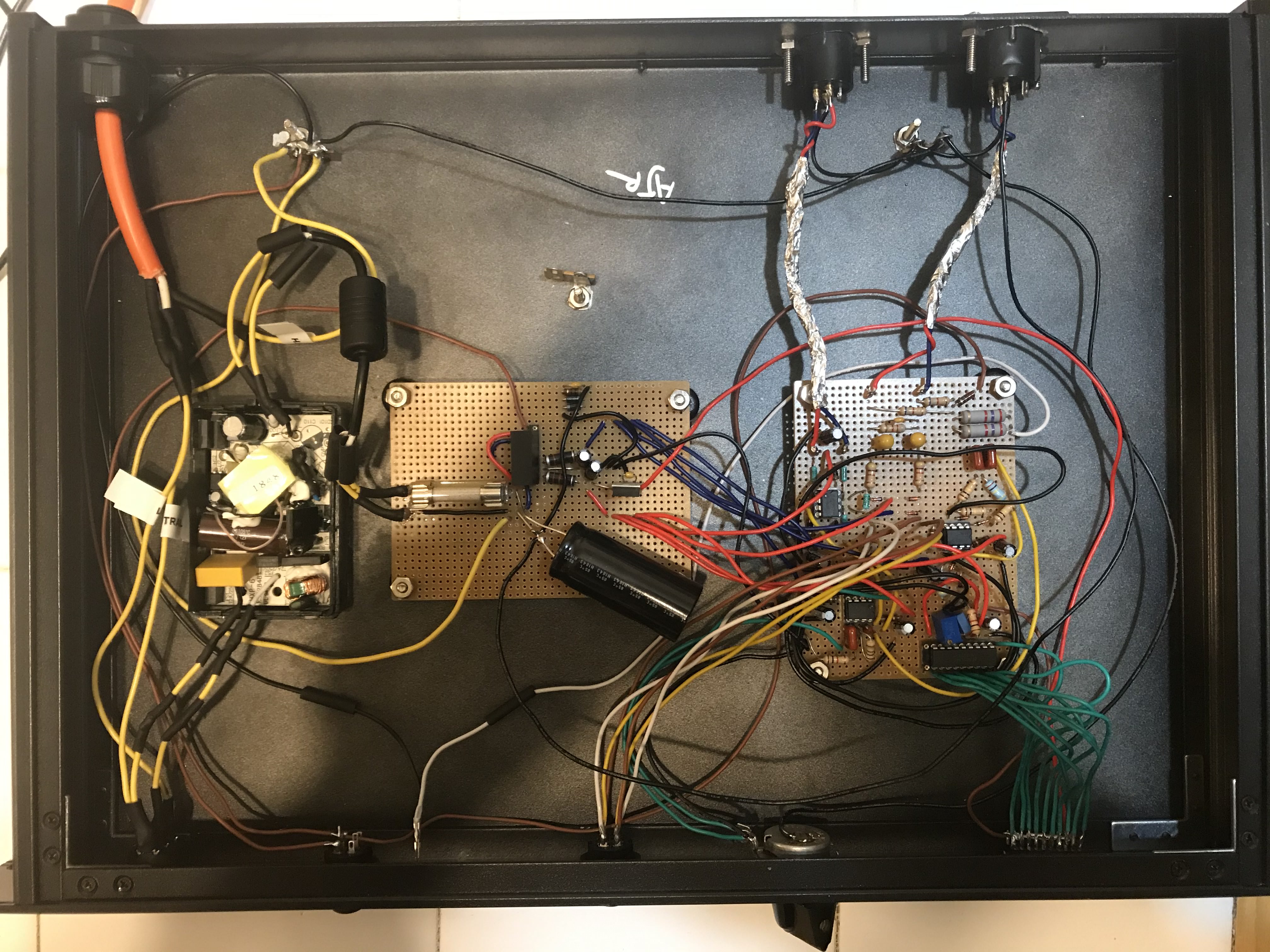
The end result and implementation process did not work as intended. After constructing a prototype of the breadboard circuit, a glaring problem arose. How is the device going to be grounded? Typically, there is an AC plug that provides an earth connection so that the chassis may be grounded; however, the wall wart that was being used only had two prongs. This meant that the steel chassis could not be safely grounded, and the shields of the balanced cable could only connect to signal ground. In order to remedy this situation, an AC plug was used along with a larger steel, rack-mountable 1U server chassis. The wall wart was disassembled, and the internal circuit was inserted into the enclosure. The live and neutral wires of the AC plug were connected to the inside of the wall wart, and the earth connection of the plug was safely connected to the bottom of the chassis.
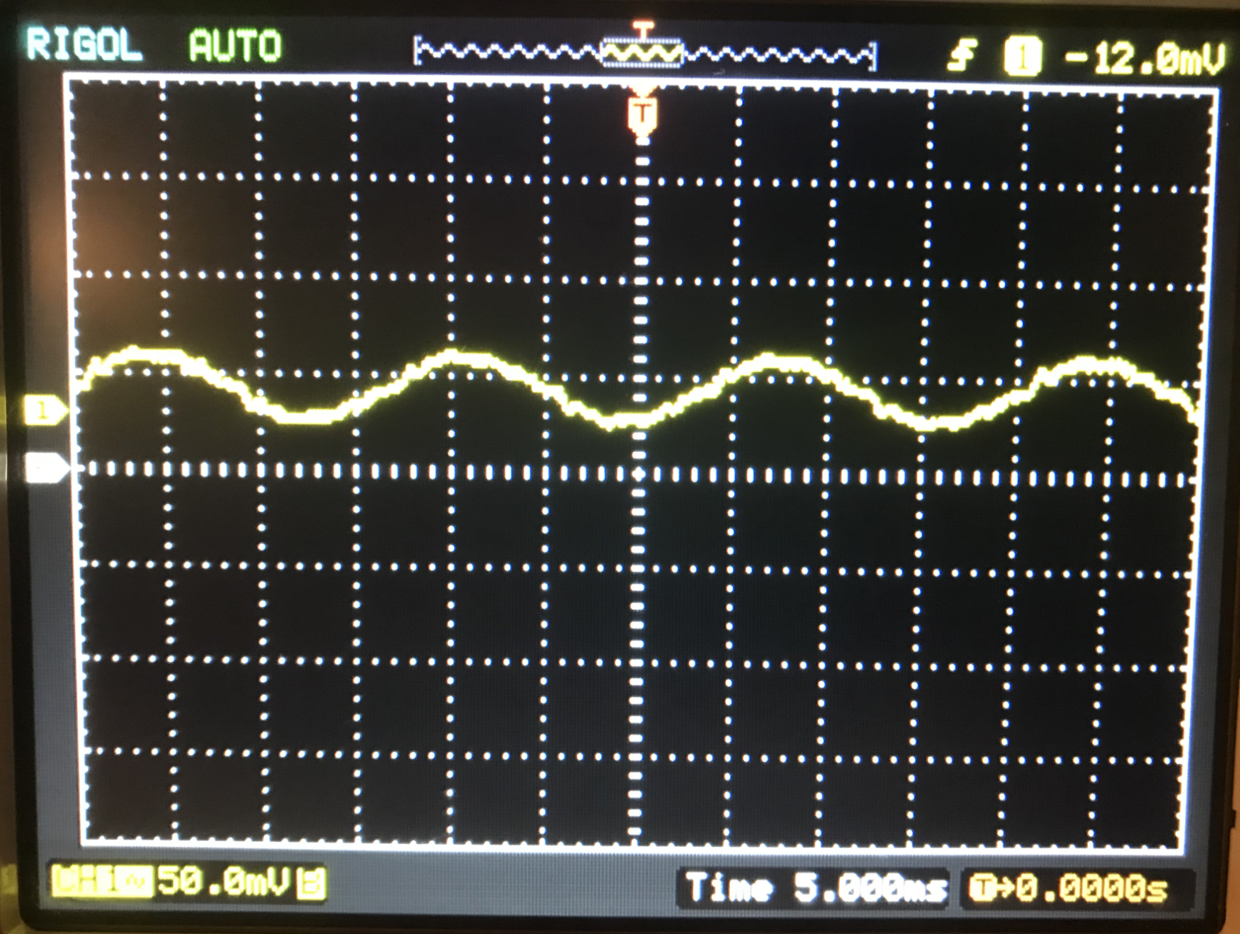
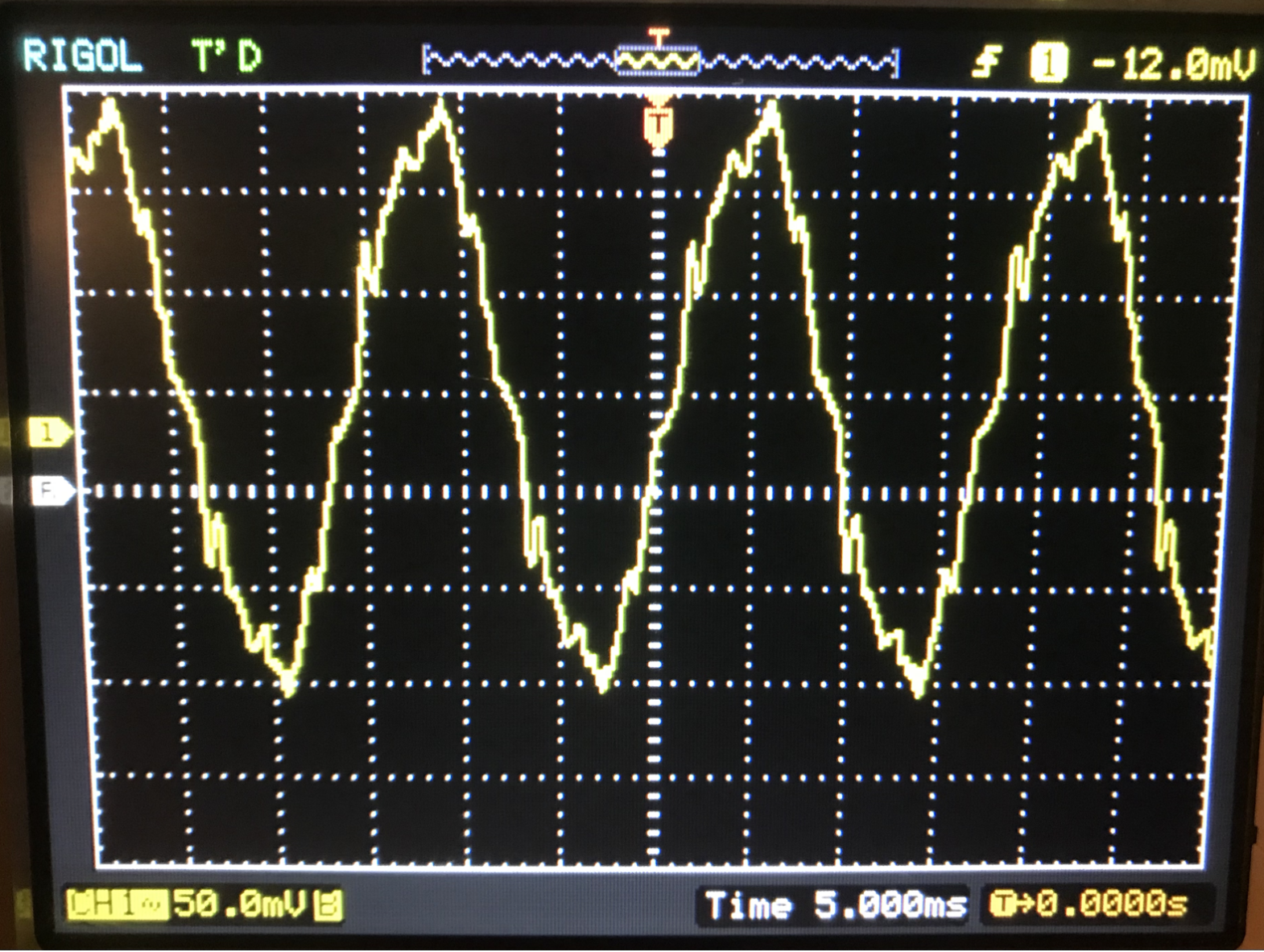
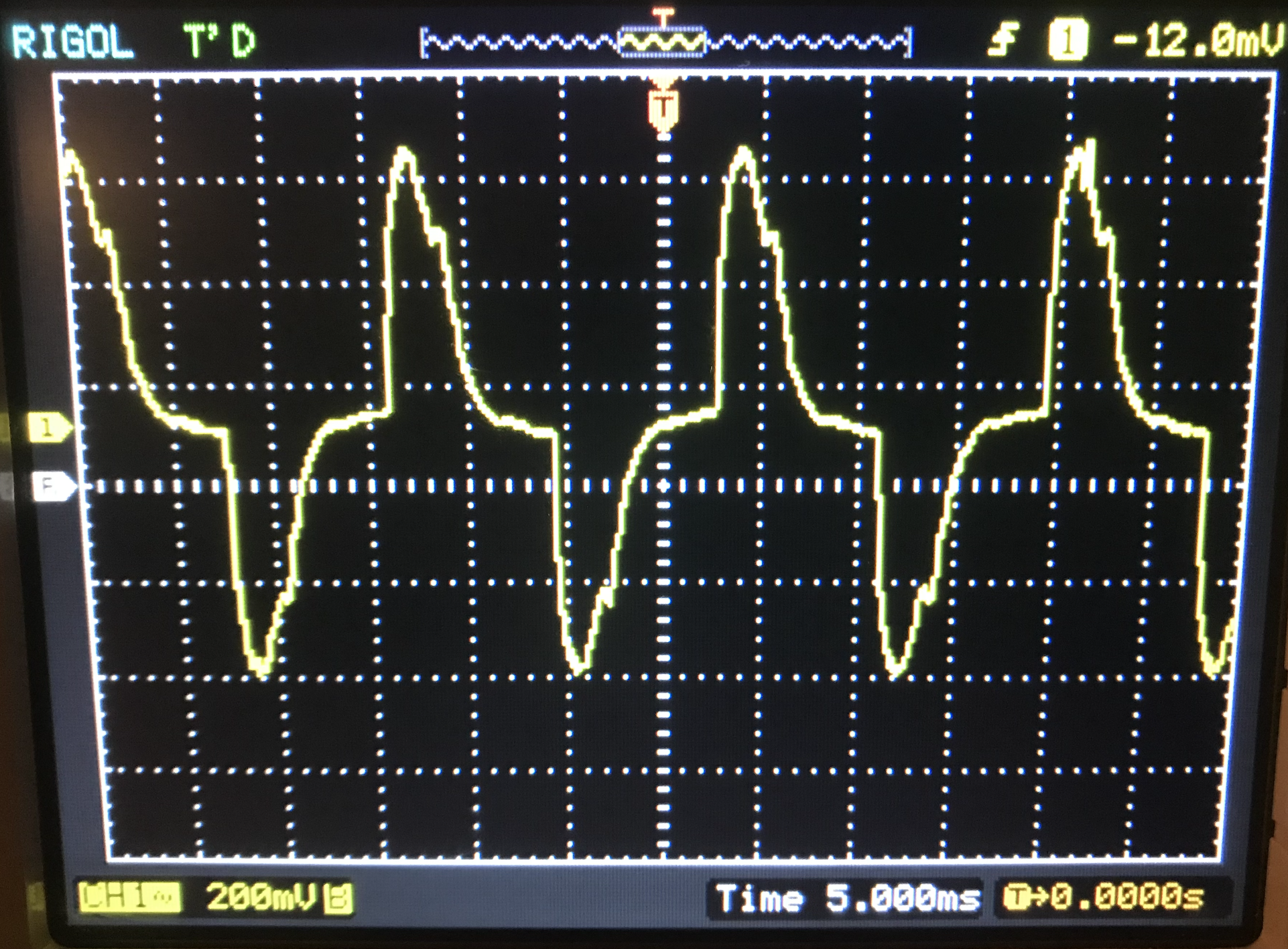
In addition to the initial problems during the implementation phase, the circuit did not function properly upon completion. When the device was first turned on, a pulsing signal appeared on the LED display. Once the device was connected to a mixing console, there was audible noise that came from the circuit. The noise was a combination of a pulsing sound, low frequency hum, and midrange hiss. The low frequency hum was most likely a result of different voltage potentials between chassis connections, so a wire was used to connect the different points together. This helped alleviate the hum, but the audio was still infected with audible hiss and a pulsing noise. Neither of the two sounds went away after a myriad of different solutions were tried. The pulsing sound is most likely due to switching of the wall wart inside the chassis. A Rigol oscilloscope was used in order to analyze the spectral content of the audio. The oscilloscope probe was grounded to the chassis and used as an antenna to pick up noise. When it was placed near the back left corner of the chassis (from a front panel perspective), some 60 Hz hum appeared on the display, as expected since the AC plug is located in that vicinity. When the probe was placed near the open wall wart, some noise started to appear on the mains voltage signal. The probe was then placed directly over the wall wart, and the 60 Hz hum became completely modulated by an alternate noise source. Even though the oscilloscope could no longer successfully identify the frequency of the signal, the subdivisions on the screen indicate that it was still around 60 Hz. The modulation became more severe when the probe was placed directly over the electromagnetic components, such as the transformer or toroidal inductor. The power supply was most likely acting as an AM radio, with the mains voltage serving as the carrier signal and the switch-mode power supply providing the amplitude information. Some shielding techniques were employed in order to stop the noise from injecting itself into the signal path, but it was not sufficient enough to ameliorate the audio quality. The device was successfully able to reproduce an acoustic signal after it was integrated into a signal chain; however, the signal quality was severely compromised, with the audio displaying an overlay of distortion.
Image Gallery
 Interior View (Internal Wiring)
 Front Panel View (Controls)
 Back Panel View (I/O)
 60 Hz Hum in Chassis Enclosure
 Noise Near Wall Wart
 Modulation Near Transformer